Architecting the Deployment: A Step-by-Step Guide to Mobile Crusher Setup
A mobile crushing circuit is a synchronized physics engine temporarily anchored to the earth. During a deployment audit at a highway infrastructure project in Peru this August 2025, the contractor had successfully towed their equipment onto the site but failed the kinematic setup. The primary jaw was surging, and the secondary cone was vibrating violently due to an un-leveled chassis. Executing a Step-by-Step Guide to Mobile Crusher Setup requires moving beyond basic assembly; it demands the architectural synchronization of multiple 250 kW machines. If the physical layout ignores volumetric mass balance or compromises hydraulic stability, the expenditure per shift will hemorrhage through mechanical fatigue before the first ton of aggregate is sold.
Step 1: Topographic Isolation and Chassis Leveling
Operating a high-inertia rotor on a tilted axis guarantees catastrophic bearing failure.
The foremost critical step in deploying wheeled units like the NK series is isolating the chassis from kinetic vibration. Once the semi-truck positions the plant, the heavy-duty hydraulic support legs must be deployed to physically lift the axles off the pneumatic tires. The tires must carry absolutely zero crushing weight during operation.
Using laser or digital inclinometers, the chassis must be leveled to absolute zero. Operating off-axis by even 3 degrees disrupts the internal fluid dynamics of the thin-oil lubrication station. If gravity pulls the oil away from the upper thrust bearing, the 250 kW eccentric shaft will suffer thermal seizure within hours, destroying the hardware amortization cycle.
Step 2: Synchronizing the Inter-Machine Surge Buffer
A multi-machine layout is inherently fragile if physically coupled too tightly. When connecting an NK75J primary mobile jaw to an NK300H secondary mobile cone, operators frequently position the discharge belt directly over the secondary hopper to save space. This is a volumetric error.
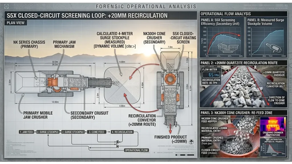
Architects must mandate a 3 to 5-meter transfer gap to establish a surge buffer (a small intermediate stockpile). The primary jaw processes raw boulders erratically based on dump-truck arrivals. The secondary cone requires a constant, uninterrupted “choke-feed” to execute efficient laminated crushing. The surge buffer acts as a volumetric shock absorber, translating chaotic primary output into a smooth, continuous feed for the secondary stage.
Step 3: Closed-Circuit Calibration and Power Integration
A flow chart is merely a theory until backed by rigid hardware tolerances and electrical continuity.
| Setup Phase | Action Protocol | Kinetic Objective | Risk of Failure |
|---|---|---|---|
| Chassis Deployment | Extend Hydraulic Legs to 0° Tilt | Isolate vibration from axles | Main bearing oil starvation |
| Inter-Machine Spacing | Establish 3-5m Surge Buffer | Guarantee choke-fed secondary | Severe aggregate flakiness |
| CSS Calibration | PLC automated gap setting | Lock maximum aggregate top-size | Screen mesh blinding |
| Power Integration | Engage Dual-Power (if Tracked) | Stabilize 250 kW utility draw | High-amp motor stall |
Before introducing raw boulders, operators must calibrate the Closed Side Setting (CSS) via the automated PLC. Setting the CSS too tight on the secondary cone will instantly choke the parallel zone, causing the hydraulic relief valves to trip. Setting it too wide will flood the integrated vibrating screen, causing the recirculating load to spike past 35% and paralyzing the entire circuit.
Mobile Circuit Integration: Commissioning Thresholds
- Chassis Leveling Tolerance: < 1 degree deviation permitted
- Surge Bin Capacity: Sized for minimum 3 minutes of continuous secondary feed
- Thin-Oil Baseline: Oil temperature must verify >25°C before startup
- Recirculating Load: Screen mesh calibrated for 20% return loop
- Power Transfer (Tracked): Transition from diesel tramming to grid power confirmed
Step 4: Dual-Power Commissioning (Tracked Variants)
For operations deploying crawler-tracked mobility (such as the Vertex VTJ1180DP), the setup protocol includes power transition logic. Tracked units excel at navigating 20-degree gradients to reach the blast face. However, crushing rock via diesel-hydraulic power continuously drains the expenditure per shift due to high fuel costs.
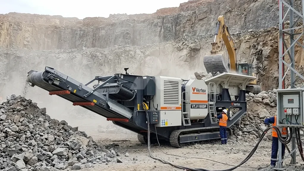
The correct setup sequence requires the operator to tram the machine into position on diesel power, execute the leveling protocol, and then immediately switch the PLC to external grid power. This dual-power commissioning stabilizes the utility draw and protects the operation against localized diesel supply chain disruptions.
Enforce Setup Protocols to Accelerate Amortization
Deploying heavy machinery requires absolute respect for thermodynamic and kinematic boundaries. Executing this Step-by-Step Guide to Mobile Crusher Setup transitions a site from barren ground to a high-capacity aggregate engine in under 24 hours. If you bypass chassis leveling or fail to engineer a volumetric surge buffer between your primary and secondary units, your expenditure per shift will be consumed by mechanical fatigue and chronic bottlenecks. Enforce architectural synchronization immediately to secure your capital payback velocity.