Deconstructing Fluid Dynamics in Silica Sand Processing Flow & Equipment Selection for Maximum Recovery
Iron Contamination and Autogenous Crushing
Steel friction destroys the chemical value of high-grade silica.
I constantly reject flowcharts from amateur designers who specify standard impact crushers for quartz reduction. Processing 200MPa silica quartz using standard steel impactors introduces unacceptable iron contamination. The abrasive silica acts like a grinding wheel against the high-chrome blow bars, shaving microscopic metal fragments directly into your product. If this sand is destined for glass or photovoltaic manufacturing, it will be rejected instantly.
The architecture must eliminate rock-on-metal friction.
The VSI6X vertical shaft impactor must be configured for “rock-on-rock” autogenous crushing. Instead of striking steel anvils, the incoming silica is accelerated centrifugally and hurled into a stationary, trapped layer of its own material lining the deep-cavity rotor. The silica grinds against itself. This kinetic lamination achieves the required particle reduction while preserving the absolute chemical purity of the sand, stabilizing the initial stage of your circuit amortization cycle.
Hydrodynamic Turbulence and Slime Loss
Crushing the rock correctly is only the first hurdle. The true failure point of most silica plants occurs in the washing phase. A single XSD3016 wash wheel processing 100 tph of crushed silica experiences massive fluid turbulence. To clean that volume of rock, you must pump a massive volume of water into the tank.
This high water velocity prevents the finest silica particles from settling.
The critical 0.15mm to 0.6mm fractions—the exact particles required to meet structural and commercial compliance—are caught in the turbulent upward flow. They are washed over the weir alongside the waste clay, causing up to 15% of the premium commercial fraction to overflow directly into the tailings pond. You are literally pumping your profit margin into a mud pit. To stabilize the hydrodynamic mass balance, you must divide the kinetic load by integrating dual XSD washers running in parallel, dropping the fluid velocity and allowing the fines time to settle.
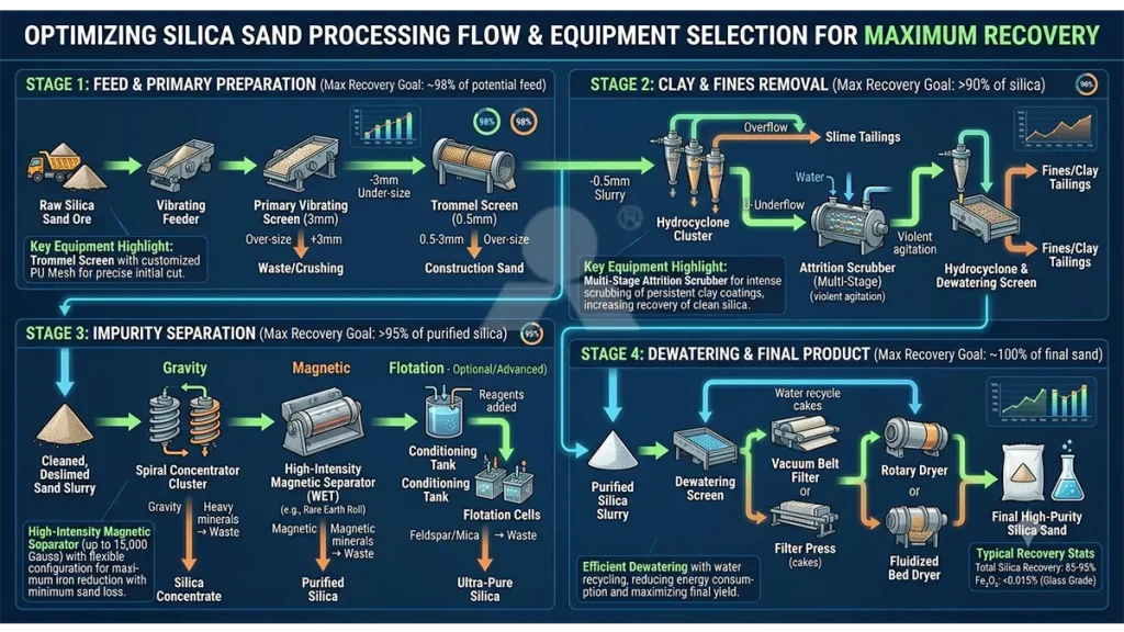
Maximum recovery demands a strict, multi-stage hydrodynamic classification matrix.
| Process Stage | Recommended Equipment | Capacity / Specs | Kinetic Function |
|---|---|---|---|
| Chemical Preservation Crushing | VSI6X1040 | 264-515 tph | Rock-on-Rock Autogenous Shape |
| Primary Decantation Wash | Dual XSD3016 | 50-100 tph (Each) | Fluid Velocity Reduction |
| Centrifugal Fine Recovery | Hydrocyclone Matrix | Matched to Weir Overflow | 0.15mm Particle Extraction |
Observe the integration of the Dual XSD3016 configuration. By splitting the 100 tph load across two 15kW machines, you fundamentally alter the fluid settling dynamics, immediately increasing the capture rate of the impeller blades.
Centrifugal Extraction and Moisture Squeezing
Even with dual washers, some fines will inevitably escape. To enforce absolute maximum recovery, the architecture must integrate a secondary hydrocyclone stage. High-pressure pumps force the muddy overflow from the XSD tanks directly into the cyclone.
Field Note: I audited a plant in North Africa where the operator refused to install hydrocyclones. Testing their tailings pond revealed it contained 18% pure, sellable silica. They were literally burying their profits. We installed a cyclone bank and their daily yield velocity jumped instantly.
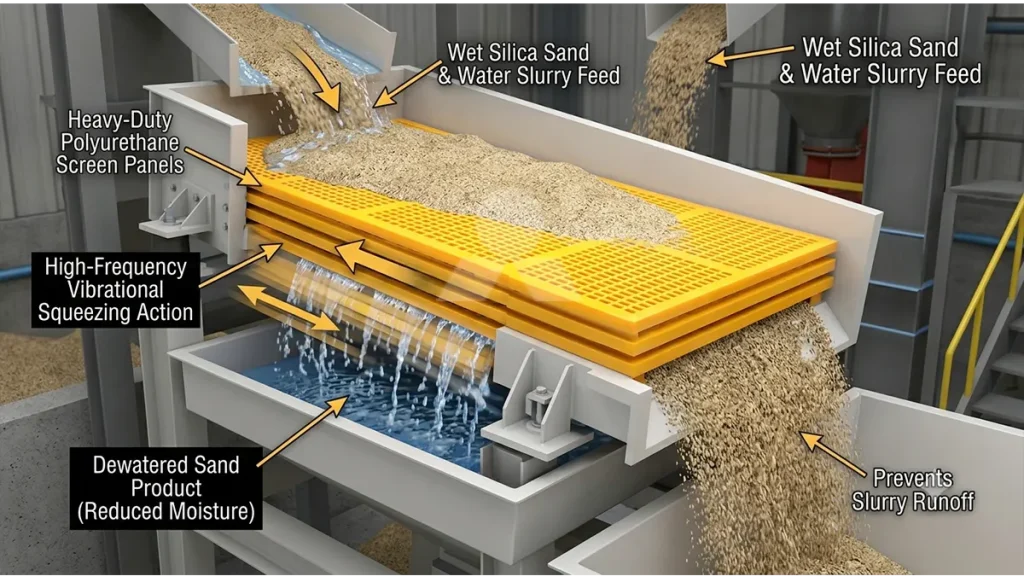
The centrifugal force inside the cyclone violently separates the ultra-light clay from the sand. The clay is ejected out the top, while the dense 0.15mm-0.6mm silica fines are forced down through the apex nozzle. However, discharging wet silica sand directly onto a stockpile results in massive product loss due to slurry runoff. A high-frequency polyurethane dewatering screen must be placed immediately post-wash. The 2G vibrational acceleration physically squeezes the water out, dropping moisture content to <15% for immediate, zero-loss truck loading.
Silica Wet Processing: Hydrodynamic Thresholds
- System Mass Flow: 95-108 tph continuous closed-circuit extraction
- Wash Tank Velocity: Halved via dual XSD3016 parallel integration
- Centrifugal Recovery: 100% capture of the >0.15mm overflow fraction
- Dewatering Acceleration: Dual-motor high-frequency kinetic squeeze
- Final Moisture Content: Strictly reduced to <15% prior to stockpiling
Enforce Hydrodynamic Extraction Discipline
A maximum recovery silica circuit is governed by the unyielding laws of fluid dynamics. You cannot bypass the recovery stages to lower your initial procurement budget. Attempting to wash 100 tph of high-purity silica in a single tank without centrifugal classification guarantees a massive, invisible hemorrhage of your most valuable fines into the sludge pond. The architecture must mandate dual XSD washers to kill the fluid velocity, followed strictly by hydrocyclone recovery and high-frequency dewatering. If you execute an open, unclassified washing circuit next month, the resulting mass balance deficit will permanently cripple your metallurgical yield velocity.